
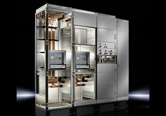
Designing and sizing a busbar
Having significant implications for the design and performance of the copper busbar system, the introduction of the IEC 61439 switchgear and control standards, is an area which design engineers need to appreciate, not least because the new testing regime and the requirement for compliance has changed the way we think about the selection of the busbar system.
There are a number of key factors relating to the design/layout stage of an assembly:
Where to put the busbar
The decision as to where to put the busbar depends on the location of the incoming cables and the position of the incoming protection device.
The form rating helps determine the layout of the assembly, the position of devices such as the circuit breaker, terminals and the busbar system, as well as whether the busbar requires a cover.
Ultimately, the size of the enclosure will be dependent upon both the form rating and the busbar system fitted.
Current rating
The total load has to be pre-calculated as this impacts on the size of the busbar. Consideration must also be given to the IEC 61439 standards because under certain circumstances it requires a rating of 125% of the full load current.
Knowing the current loadings means that watt loss can be calculated which will in turn have a direct impact on temperature rises within the enclosure. Again, this is a key element of the standard, along with the maximum temperature ratings.
Connections
Connecting conductors to the busbar can cause problems for contractors as any oversized cables may be too large to terminate on the busbar system.
Design engineers need to consider this possibility and compensate with different busbar adaptors or terminals. But, remember that any additional copper connections may invalidate the busbar warranty as they could be considered to be extending its capability beyond the tested system.
Under the standard, all copper connections above 1,600A have to be tested for impact of heat rise on the air circuit breaker. In addition, the connections from and to the main busbar system have to be physically tested by the original equipment manufacturer of the switchgear system. Essentially, the panel builder cannot make their own.
Fault ratings
High-fault currents (short-circuits) can obviously be highly destructive. The initial electro-mechanical force generated in fault conditions can be huge - tens of thousands amps. As a consequence, the busbar system must be robust enough to carry the current until the short-circuit protection device (such as a fuse or MCCB) trips.
Design engineers have to be aware of the fault rating from the outset, a level that is determined by several factors: the size of the supply transformer; the impedance of cables from the transformer; and current limiting effects of the protection device. The fault rating can be given as either a RMS kA - which typically has a time withstand value of one second - or a peak value measured in kA.
Instructions around how to install the busbar support are the responsibility of the original manufacturer of the switchgear system and issues such as the spacing of the busbar supports are determined by the manufacturer’s testing.
These distances are governed by the fault level and the size of the copper bar. Spacing (ie. how far they are apart) has a major bearing on the strength of the system; if the supports are fitted too close to each or too widely distant, then the system’s performance under fault conditions could be badly affected.
Similar articles

More from Rittal
- Wiring processing - overnight 16th June 2020
- Climate control maintenance is the key to efficiency 23rd July 2019
- Putting Industry 4.0 theory into practice 16th May 2019
- Cloud-based cooling units for Industry 4.0 10th April 2019


Write a comment
No comments