
Contactors For Capacitors
There’s a bit more to choosing contactors for use in power factor correction systems than might at first be apparent, says Steve Rickard of Moeller Electric.
The capacitors used in power factor correction (PFC) systems are improving all the time, and the latest types have much lower internal resistance and inductive impedance than their predecessors. This makes them better at the job for which they are designed, but it also makes them a more difficult load to switch, because there’s less impedance to limit the inrush current as the capacitor charges.
To see what this means in practice, it’s important to note that there are, in the main, two types of PFC system. The first type is used with an individual load, and is typically a single capacitor installed close to that load. The second type corrects the power factor for a whole site or plant, and uses multiple capacitors switched in stages. It is often installed near the main distribution board.
With single-load PFC systems, the capacitor draws its charging current only from the mains supply. In addition, since it is near the load and remote from the distribution board, the impedance of the supply cables will tend to limit the charging current. For these reasons, the current peak when the capacitor is switched can be expected to be no more than about 30x the capacitor’s steady state operating current (In).
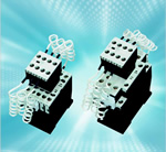
Since this peak is relatively small and only lasts for a few milliseconds, it is usually possible to use standard contactors, such as those in the Moeller Electric DIL-M range, for applications of this type. In most cases, the capacitor and the load itself will be parallel connected and switched with the same contactor.
The situation is very different in multi-stage, multi-load PFC systems installed close to the supply source. Here not only is the impedance of the supply cables much lower, the capacitors have a second source of charging current – from other capacitors in the bank that are already charged. The result is that switching peaks of 150xIn or even more are by no means unusual.
If ordinary contactors are used for this type of switching, the large current peaks quickly strip out the material that the manufacturers add to the contact alloy to prevent contact welding. The result is that, after only a few hundred switching operations, pure silver is all that remains and the contacts inevitably weld.
To address this issue, Moeller Electric produces DILK contactors that are specifically designed for severe capacitive load switching duties. The same size as ordinary DILM contactors and compatible with the same accessories, these contactors use a special anti-weld contact material. In addition, they also have integral series resistors, and make provision for pre-charging the capacitors via early-make auxiliary contacts.
These optimised contactors are the best choice for use with capacitor banks but if it is essential to use standard contactors, this is possible provided that inductors of 5µH or more are added between the contactors and the capacitors. This corresponds approximately to air-cored inductors with four turns and a diameter of 14cm.
There is, however, another slight twist to this story. The high levels of harmonics often present in supplies as the result of connecting numerous “electronic” loads can result in excessive currents flowing in power factor correction capacitors. To eliminate this problem, suppliers of PFC systems – particularly multi-load types – are starting to build chokes into their products.
Though it is not their primary function, these chokes substantially reduce the charging current peaks when the capacitors are switched, which means that, in many cases, standard contactors can be used without the need for additional inductors.
It’s not all good news, however, as for dependable service, the contactors must have a thermal rating equal to 150% of the capacitor on load current, in order to conform with the requirements of IEC60931-1. This also applies when standard contactors are used in conjunction with auxiliary inductors.
There’s one final point worth considering in relation to contactors used in multi-stage PFC systems. Inspection of the system while it’s in operation will usually show that many of these contactors are almost permanently closed, and only a very few switch regularly. Since equalising the number of switching operations between contactors will lengthen the lifespan of the equipment, it is useful to design the control circuitry so that the operating sequence of the contactors is regularly rotated.
Power factor correction is an important aid in minimising energy bills and eliminating wasted power. Fortunately, PFC systems are cost-effective, easy to install and, provided that the contactors used in them are correctly specified, they are very reliable. Hopefully, this short piece has given some useful guidance on making the right contactor choices.
Similar articles

More from Eaton Corporation
- IP-based automation system for underground applications 20th November 2020
- Engineering expertise keeps the blades turning 28th September 2020
- Blowout preventer hoses exceed the latest fire test requirements 9th October 2019
- Enhancing configuration software and increases flexibility 15th May 2018


Write a comment
No comments