
Performance and longevity improved through dynamic balance
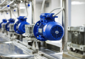
It is crucial for high speed precision motion systems to be dynamically balanced; otherwise they will vibrate in use, lose precision, suffer excessive wear and fail prematurely. Here, Ian Carr of Drive Lines Technologies in Bedford reviews procedures and techniques for balancing high speed precision couplings.
Precision drive systems are generally required to have a relatively long working life, during which they must maintain their ability to perform accurately. Excessive vibrations within the system would compromise these goals of longevity and precision, so motion system builders know they have to be finely balanced.
Preferably each component in a drive system will be balanced, so will not induce vibration into the drive line. To achieve this balance the mass of the component must be evenly distributed about the centre of the shaft so that it maintains an even centrifugal force about the axis of rotation.
If a component is not balanced it will vibrate in use, the magnitude of the centrifugal force causing the vibration being proportional to the distance of the centre of mass of the component from the axis of rotation. Identifying the centre of mass may seem like a daunting prospect, but because couplings and other rotating components are usually round and rotationally symmetrical it is a relatively easy task,
A simple technique is to think of static balance about an axis, similar to an old- fashioned balance scale or a see-saw. An eccentric rotating mass works in essentially the same way: during each rotation, the centre of mass effectively moves towards and then away from the axis of rotation. Thus the centrifugal force increases and decreases in proportion to the instantaneous degree of rotation.
If memories of school are not too painful, one may recall that in physics lessons one learned the moment of inertia calculation:
I = mr2 (inertia = mass times radius squared)
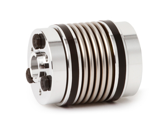
Imbalance of essentially round couplings and other rotating components comes into play when additional parts such as clamping screws or shaft keys are added. Also, it is possible for the manufacturing processes to cause imbalance due to imperfections such as a tiny air pocket in a casting. Clearly, adding or subtracting mass in one area of a part causes imbalance, which can be corrected by adding or subtracting compensating mass on the opposite side of the part.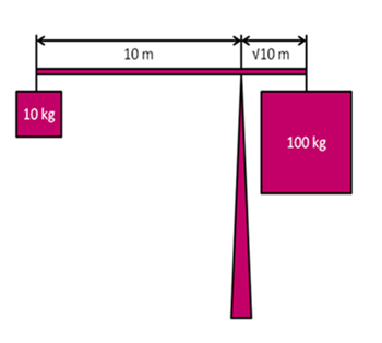
A simple way to do this is to drill holes into the body of the component. Typically these are positioned near the outside diameter so that less material will need to be removed, thus preserving the structural integrity as much as possible.
Manufacturers of precision parts such as coupling hubs may design-in balancing holes to compensate for asymmetries within the hub, while system builders may need to drill further holes to account for the inertial effects of additional drive components.
It should be noted that precision couplings are designed and supplied with a speed rating. Quality small to medium sized machined couplings typically come with a speed rating of about 10,000rpm, which means they can be balanced for speeds between about 20rpm and 80,000rpm. Larger couplings will not be used on very high speed applications, but can be balanced within their expected speed ranges.
It is also important to understand that there are other issues that also have to be considered, such as torque transfer at high speed. For example, centrifugal forces at high speeds may cause holding screws to loosen or clamps to open, for which engineers must find a solution, such as using conical clamping rings that offer better symmetry and more even stress distribution.
Downloads
Similar articles

More from Drive Lines Technologies Ltd
- Linear drive solutions offer independent and precise sub-systems 11th October 2017
- High performance bevel gearbox range extended with new size 18th September 2017
- Mechanical Backlash: How much is too much? 5th September 2017
- Performance and longevity improved through dynamic balance 7th August 2017


Write a comment
No comments