
Control Valves fit Common Motor Port Pattern
29th July 2008
Source:
Integrated Hydraulics Ltd
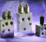
Mounting hydraulic control valves directly to the ports of a hydraulic motor saves space, simplifies installation and places the valve in the best position to provide protection and/or control. Using cartridge valves located in a motor mounted body enables the designer to select from a remarkable range of variants to obtain the optimum performance from the system as a whole.
These valves, designed for the most common port patterns, bolt directly onto the motor eliminating the need for steel pipe or hose between valve and motor thus reducing installation time, removing the cost of connectors and pipework and minimising the overall size of the motor/valve package. Cartridge valves are used in the block and because an extensive range of overcentre cartridges using the same cavity is available, the most appropriate design; Standard, Part Balanced, Balanced or Counterbalanced; pressure range and pilot ratio can be selected to give the best possible performance and stability from the system.
Overcentre valves give static and dynamic control of loads by regulating the flow into and out of the hydraulic motor. They will stop runaway (even in the event of a hose burst) and if open centre directional control valves are used, will give thermal expansion relief of the hydraulic fluid.
The integral check section allows free flow into the motor then holds and locks the load against movement. The pilot assisted relief valve section will give controlled movement when pilot pressure is applied. The relief section is normally set to open at a pressure at least 1.3 times the maximum load induced pressure, the pressure required to open the valve and allow movement depends on the pilot ratio, for optimisation of load control and energy usage a choice of pilot ratios is available.
For use on smaller motors Integrated Hydraulics 1CE*30 cartridge is used. It is suitable for flows up to 30L/min and is available in four versions. The Standard version has two pressure ranges, one to 210 bar the other to 350 bar both pressure ranges have 2.5:1, 5:1 and 10:1 pilot ratio options. The Part Balanced version, in which the poppet is partially balanced from the effects of pressure in the valve line has one pressure range, up to 350 bar and 2.5:1 and 4:1 pilot ratio options. Valve line pressure has no effect on the poppet in the Fully Balanced version, which again has one pressure range, to 350 bar and one pilot ratio, 5:1. The Counterbalanced model has three standard pressure ranges, 220, 280 and 350 bar, the primary pilot ratio is 4.3:1 and the secondary 0.4:1. The Counterbalanced valve will maintain a back pressure in the motor until the pressure in the inlet line acting on the secondary pilot area is sufficient to overcome the force of the spring.
For larger motors the 1CE*90 cartridge with flows to 90 L/min is employed. The Standard, Part Balanced and Fully Balanced valves have two pressure ranges, up to 225 bar and 350 bar and two pilot ratio options, 4:1 and 8:1. The Counterbalanced option again has two pressure ranges, up to 350 bar and 380 bar but has a primary pilot ratio of 5.6:1 and secondary pilot ratio of 0.7:1.
Blocks are available with a built-in brake release shuttle that will disengage a static brake regardless of which line is under pressure. Incorporating this function into the block saves installation time, cost and complexity and eliminates more potential leak paths.
Integrated Hydraulics Motor Mounted Overcentre valve blocks offer exceptional flexibility not only because of the range of cartridges available but also through the use of cavity plugs that can be used to change a block from a dual to a single overcentre with control in either line “A” or “B”. Single valves are normally used when the load is unidirectional, for example on a winch and dual versions for controlling loads in both directions, for instance on drive systems.
For most applications the standard, high strength aluminium body is suitable, but for pressures over 210 bar or particularly arduous conditions a steel body may be preferable.
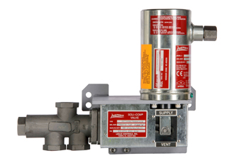
Integrated Hydraulics Limited also manufactures motor mounted Cross Line Relief valves. These are designed to protect both lines in a circuit from over pressurisation by relieving oil from the high to the low pressure line. The company’s cross line relief valves use a single, differential area, poppet type cartridge which offers reliable, fast acting performance.
In operation, pressure acts over one of two equal differential areas, either will force the poppet back against the spring allowing relief flow from the high to low pressure port. Pressure is adjustable from 114 to 350 bar and as the differential areas are equal it will be the same in either direction. Maximum flow through the valve is 150 L/min and, being of the poppet type, internal leakage is minimal at 5 millilitres/min.
Overcentre valves give static and dynamic control of loads by regulating the flow into and out of the hydraulic motor. They will stop runaway (even in the event of a hose burst) and if open centre directional control valves are used, will give thermal expansion relief of the hydraulic fluid.
The integral check section allows free flow into the motor then holds and locks the load against movement. The pilot assisted relief valve section will give controlled movement when pilot pressure is applied. The relief section is normally set to open at a pressure at least 1.3 times the maximum load induced pressure, the pressure required to open the valve and allow movement depends on the pilot ratio, for optimisation of load control and energy usage a choice of pilot ratios is available.
For use on smaller motors Integrated Hydraulics 1CE*30 cartridge is used. It is suitable for flows up to 30L/min and is available in four versions. The Standard version has two pressure ranges, one to 210 bar the other to 350 bar both pressure ranges have 2.5:1, 5:1 and 10:1 pilot ratio options. The Part Balanced version, in which the poppet is partially balanced from the effects of pressure in the valve line has one pressure range, up to 350 bar and 2.5:1 and 4:1 pilot ratio options. Valve line pressure has no effect on the poppet in the Fully Balanced version, which again has one pressure range, to 350 bar and one pilot ratio, 5:1. The Counterbalanced model has three standard pressure ranges, 220, 280 and 350 bar, the primary pilot ratio is 4.3:1 and the secondary 0.4:1. The Counterbalanced valve will maintain a back pressure in the motor until the pressure in the inlet line acting on the secondary pilot area is sufficient to overcome the force of the spring.
For larger motors the 1CE*90 cartridge with flows to 90 L/min is employed. The Standard, Part Balanced and Fully Balanced valves have two pressure ranges, up to 225 bar and 350 bar and two pilot ratio options, 4:1 and 8:1. The Counterbalanced option again has two pressure ranges, up to 350 bar and 380 bar but has a primary pilot ratio of 5.6:1 and secondary pilot ratio of 0.7:1.
Blocks are available with a built-in brake release shuttle that will disengage a static brake regardless of which line is under pressure. Incorporating this function into the block saves installation time, cost and complexity and eliminates more potential leak paths.
Integrated Hydraulics Motor Mounted Overcentre valve blocks offer exceptional flexibility not only because of the range of cartridges available but also through the use of cavity plugs that can be used to change a block from a dual to a single overcentre with control in either line “A” or “B”. Single valves are normally used when the load is unidirectional, for example on a winch and dual versions for controlling loads in both directions, for instance on drive systems.
For most applications the standard, high strength aluminium body is suitable, but for pressures over 210 bar or particularly arduous conditions a steel body may be preferable.
Integrated Hydraulics Limited also manufactures motor mounted Cross Line Relief valves. These are designed to protect both lines in a circuit from over pressurisation by relieving oil from the high to the low pressure line. The company’s cross line relief valves use a single, differential area, poppet type cartridge which offers reliable, fast acting performance.
In operation, pressure acts over one of two equal differential areas, either will force the poppet back against the spring allowing relief flow from the high to low pressure port. Pressure is adjustable from 114 to 350 bar and as the differential areas are equal it will be the same in either direction. Maximum flow through the valve is 150 L/min and, being of the poppet type, internal leakage is minimal at 5 millilitres/min.
Similar articles
More from Integrated Hydraulics Ltd
- Control Valves fit Common Motor Port Pattern 29th July 2008
- NEW, 90 litre, 2 Way Bi-Directional Poppet Valves 13th February 2008


Write a comment
No comments