
The A-Z of DC motors
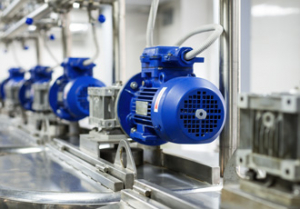
DC motors are electrical devices that draw direct current and convert it into mechanical energy. Direct current is especially useful for machines that need to be driven at variable speeds. These motors are easy to miniaturise, thus making them suitable for compact devices. They come in handy during low power and low voltage applications.
Author: Jeson Pitt, D&F Liquidators
You can even use DC motor for high-power applications that require several megawatts. They are useful in places where speed variation is needed at high performance levels without complicated motor control systems.
How it works
An armature carrying a current, which is connected through brushes and commutator segments to the supply end, is placed between two magnets. They can either be an electromagnet or a permanent one. The North and South poles will be perpendicular to the armature.
When the current flows through this armature (using a motor starter), it will produce rotational movement.
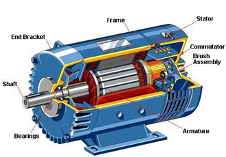
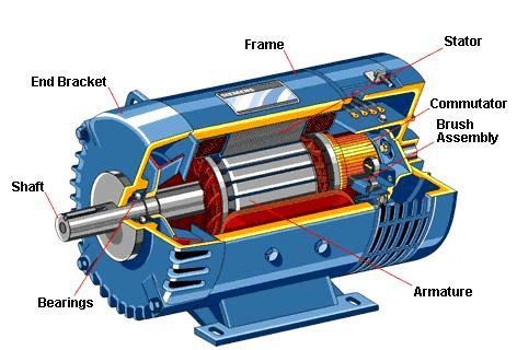
Construction of DC motor
DC motor is made of the following parts:
- Yoke: It is an outer frame that is made of cast iron or steel. It houses the DC motor and provides mechanical strength to the entire assembly. Additionally, it carries the motor’s magnetic flux that the field winding produces.
- Armature core: It is the cylindrical rotor of the machine. It has slots for the armature winding and is composed of thin laminated steel discs to reduce eddy currents.
- Armature winding: Made of copper, this winding rests in armature slots. The conductors are insulated from the core, and from each other.
- Field winding: They are connected in series across each pole. They are made of copper and are often former wound. The winding is done in a way to form alternate South and North poles when energised.
- Pole and pole shoes: Poles are bolted and welded to the yoke and they house the field winding. The pole shoes are attached to the pole assembly and they support the field coils. They spread the flux uniformly through the air gap.
- Commutators and brushes: They connect the armature winding physically. Commutators are an arrangement of copper segments that are equal in number to the armature coils. They are insulated from each other and provide the current for the armature conductors. There are carbon or graphite brushes that rest on the commutator. They slide across segments when the motor turns, to supply current and keep physical contact.
Types of DC motor
There are three types of DC motors, which are based on the types of winding:
- Series wound motors: In these, the armature coil and field coils are connected in series. You can reverse the direction of motor easily by reversing the polarities of the field coil or the armature.
- Shunt wound motors: The coils, armature and field coils are supplied with different voltages using two sources, or in parallel to match the requirements of the machine. You can reverse the direction of the motor by inverting the windings or inverting the voltage at the armature. This is the way most bidirectional DC motor speed drives operate.
- Compound wound motors: The qualities of both series and shunt motor are series wound motors. There are two windings in each field coil plate, where one is connected to the armature in parallel and the other in series.
If both amperes turns add their effect, it works as an additional flux motor, and if they work against each other, it functions as a negative flux motor. This mounting method is rarely used since it can be unstable with high loads.
The aim of circuit
The objective of the circuit of DC motor is to keep the permanent magnet DC motor running at a constant speed that is set externally. You can achieve this by monitoring the current and voltage across the brushes of the motor.
The voltage consists of two components:
- A back-EMF generated by the windings of the armature moving through the magnetic field of the motor.
- A voltage caused by the current passing through the real resistance of the windings and the brushes.
The current through the motor armature passes through a resistance (rm/10), which means, approximately 0.1 as large as the ohmic resistance of the motor. Then, the voltage across this resistance is amplified by a factor of approximately 10, and the resulting voltage is added to a second voltage in a differential amplifier, which is the voltage as measured across the two brushes of the motor.
The output of this amplifier is compared to the reference voltage (which is provided externally to the circuit and it determines the speed of rotation of the motor) in another differential amplifier. You can control the output of a power outage stage to drive the motor.
The reference voltage is compared to the back-EMF and the motor is caused to run at a constant speed set by the reference voltage. You have to superimpose a sawtooth waveform on the reference voltage to soften the switch from driving to not driving.
Similar articles

More from D&F Liquidators
- The A-Z of DC motors 5th June 2017


Write a comment
No comments