
Maintaining performance in older pumps with TLC
More than 20% of global electric motor energy consumption is accounted for by pumping applications, and conscientious plant owners have been trying to maximise the efficiency of this equipment for many years. This task is made more difficult for older equipment for which the full specification data is no longer available or has been appropriated for a new task.
Sulzer’s Jerry Ruc, looks here at some common causes of poor performance and suggests methods of improving efficiency:
Many of the pumps that are in operation today were built in the 1960’s and 70’s, which is a testament to the original design and the skill of matching the pump to the operating demands of the application. A properly specified pump will operate reliably for decades, with only a minimum of repairs needed. It is essential that designers match the conditions that encompass the entire system, typically referred to as the system curve. The pump duty point (design point) is only one point on that system curve.
As operating conditions evolve over time, so the pumping application demands also change, this can include a change in flow, media characteristics or duty. However, just because a pump is capable of operating on the outer edges of the system curve does not mean that there will not be consequences in terms of performance or reliability.
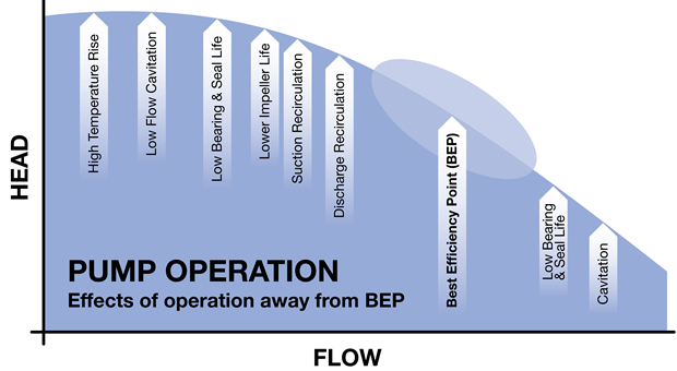
For this reason, manufacturers establish the minimum operating flow as well as listing all of the limiting design conditions, such as net positive suction head required (NPSHR), maximum flow and others. It is important to understand the consequences of dialling back pump flows which means measuring the operating conditions and calculating the point at which the pump will be operating on the system curve.
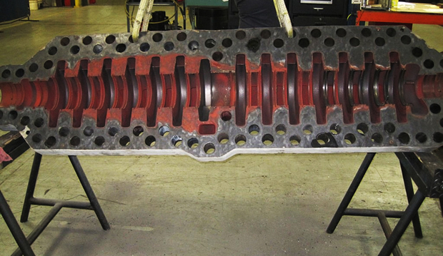
This can be illustrated by a recent repair project that was completed by one of Sulzer’s service centres. A multi-stage boiler feed pump was brought in for repair and it was immediately clear that the pump had suffered some severe damage. An initial inspection showed that the suction-side seal, several impellers, sleeves and stationary components had been destroyed. The evidence indicated that the pump had been operated at or near shutoff flow.
When a pump operates in a boiler feed system, iron oxide deposits are often found in the casing. In this case the deposits were absent in the first three stages of the pump but intact on the latter stages. This indicated that the pump had experienced a condition where the input energy from the impellers had turned the water to steam before it had a chance to exit the pump. The creation of steam in a pump is a violent condition which induces considerable vibrations and can lead to surface erosion.
Normally, the frictional losses in a pump are converted to a few degrees of heat and discharged out in the water flow. With very low or no flow, this energy builds up in the pump and eventually the heat input to the liquid builds to an amount that surpasses its vapour pressure and it becomes two phases – liquid and gas. As the input of energy increases the liquid heats to the point of transformation and turns completely into the gas phase.
Operating a pump under these circumstances is clearly inefficient and steps should be taken to properly assess the minimum flow requirements of an installation, along with remedial work to indicate when this condition is not being met. In this way pump performance and reliability will be improved.
The possible causes of the pump failure in this example were reviewed with the plant owner who was keen to avoid similar cases in the future. A number of issues were highlighted including a misunderstanding about the required flow rate of the pump. Predominantly, the plant bases calculations on steam rates so these were converted to water flows and plotted on the pump operating curve. This established that the pump was not only operating close to the minimum flow point but its pump operating curve was fairly flat at the lower flow region.
To make matters worse, the failed pump discharges into a header, along with other, similar pumps; this creates a parallel pumping system that is designed to increase system flow. The balancing act of a parallel operating system is to ensure that each pump is operating equally in terms of the flow. The main control valve will provide the necessary back pressure to locate the pumps on their curves but this works with the assumption of equal conditions at the suction point. After all, a centrifugal pump is a differential pressure device, meaning a lower suction will deliver lower discharge pressure, which will position the pump on a slightly different point of its curve.
The pumps automatically adjust their flow output to match the back pressure with the more/less pressure differences in piping and suction delivery to each, such that the total resistance at the junction of the two on the discharge is equal. Typically, the small differences are fairly easily tolerated by the pump. The problem comes when the required operating point changes and is pushed back on the curve, closer to the flat portion of the curve.
At this point the ‘weaker pump’ can be pushed back into the unstable operating region. This pump is perceived as weaker for any number of reasons such as lower suction pressure and flow, greater discharge piping restriction and certainly the wear of the internal clearances which affect the efficiency. For this reason many reliability engineers trend their equipment by position, serial number, operating hours and number of starts among other factors. Their focus is to ensure the pumps are equal in the system and that one will not have an advantage over any other.
The key to a successful parallel pumping system is to use pumps with the same shaped characteristic curve and to ensure identical operating environments for each of the pumps. This is best achieved by using the same model pump with identical impeller trims, and both set mechanically to the same OEM standards, including the internal wear parts and design clearances.
By using the same suction source for each pump the suction pressure at the entry point to each pump will be the same. The suction pipe should have same line size and length to each pump, while the valves should also be the same size and type, and in this way the friction losses are then equal for each pump.
Having addressed the suction side, the discharge pipe needs to increase to full-line size as soon as possible after the pump and if possible the discharge pipes should be symmetrical from the pumps to the point at which the lines re-join. Finally, one essential aspect that is often overlooked is the minimum flow line, which should be required for each pump. This ensures that the minimum flow condition is always satisfied, protecting the pump from overheating and subsequent damage.
Many industrial processes utilise a variety of pump designs, often from several different manufacturers and so achieving a comprehensive performance review of the installation can be difficult. As an independent specialist, Sulzer engineers offer a wealth of experience that can identify potential issues and provide a detailed analysis of both existing and proposed installations.
It is essential that process and maintenance engineers review the pumping system design in the event of a process change to ensure that it remains suitable under the new operating conditions. Pump manufacturers and specialist maintenance providers, such as Sulzer, are able to provide detailed information on existing pumps and make modifications to current systems to deliver maximum performance and reliability. Furthermore, expert advice from experienced pump engineers can help operators to maximise the flexibility of the system and ensure continued service for many years to come.
Similar articles
More from Sulzer Ltd
- Construction of Sulzer’s new Birmingham Service Centre on track 8th September 2020
- Electrical distribution powered up for holiday period 1st July 2020
- Rapid reverse engineering 18th December 2019
- The future of the oil and gas sector is now 25th October 2019


Write a comment
No comments