
The need for EMI filtering with factory automation

Increased electromagnetic interference, or EMI, can adversely affect system efficiency and increase down-time by interfering with analogue control signals and industrial communications between devices and systems.
By Dave Armitage, Schaffner USA
So, as inter- and intra- communication networks expand on the factory floor, adequate electromagnetic compatibility or EMC design objectives need to be addressed. Electromagnetic compatibility is the ability of a machine to operate in its intended electromagnetic environment.
Detecting EMI can be difficult and time consuming at the system level as any factory automation project is completed, therefore, time and trouble can be saved if proper noise mitigation solutions are implemented into the design process.
The appropriate solution(s) can control the 'flow' of electrical energy in and out of devices/systems and the appropriate physical infrastructure solution(s) can manage EMI issues between devices/systems.
In many cases, control/signal cables placed in control panels can disrupt communications and control functions of an entire automation system and cause the failure of the installation.
Potential sources of EMI
Due to the close proximity of sensitive devices to noisy sources, the leading modes of EMI are capacitive and inductive coupling amongst cabling and harnesses. Understanding this helps to examine how best practices and specifying noise mitigating products can improve the situation.
Generally, the noise coupling is unintentional and occurs when current flowing through one wire induces a voltage on a parallel wire. Capacitive coupling is more of a concern in high voltage circuits, while inductive coupling is more of a concern in high current circuits.
To reduce or control this coupling, it’s typically recommended to keep a distance of three to six inches between high voltage and low voltage conductors that run in parallel to each other. Conductors that run perpendicular to each other are not subjected to the same levels of EMI. Twelve inches is a typical distance between encoders or resolver feedback cables and motor, or any AC power cables.
Some common industrial sources of noise can be servo drives, variable frequency drives, switching power supplies, inductive loads, lighting, and static electricity. Rotating machinery can generate a significant amount of electrical noise. Servo drives can also create noise due to voltage dips and spikes caused by switching current flow on and off at high frequencies.
Switching power supplies can also emit EMI and at a much higher level than linear power supplies. Turning inductive loads on and off rapidly can produce a spark across an electrical contact which can generate EMI. This arcing and sparking can cause a wide bandwidth of EMI.
Even lighting can generate EMI, in this case due to quick changes in voltage or current. Another source of EMI is static electricity and related electrostatic discharge. Nylon or other polymer-based conveyor belts often are used to move material in industrial facilities and can generate high amounts of static electricity.
It should be kept in mind that any length of wiring can and usually will act as an antenna, including the AC power wiring. A simple rule of thumb is the longer a wire is, the better an antenna it becomes.
One reason to be cognizant of EMI and its effects is that WLANs are becoming more common in industrial facilities. EMI is a difficult issue to harden a network against. Proper design methods will significantly aid in producing a clean RF environment.
Components affected by EMI
There are many types of components that can be affected by EMI in industrial applications. These include analogue signals, measurement instrumentation, communication networks, and microprocessors. Encoders rely on low level signals from rotating machinery and can be especially susceptible to EMI.
Symptoms include encoder counts changing with no motor rotation and non-repeatable position moves. Tachometers may show similar symptoms, such as incorrect speed readings and unexpected speed fluctuations.
Sources of electrical noise near sensitive analogue signals and measurement instrumentation often can cause symptoms such as unexpected voltage spikes and ripple or jitter causing incorrect or non-repeatable readings.
With communication networks such as Ethernet links, electrical noise symptoms usually include loss of communication or errors in data. And with Programmable Logic Controllers (PLCs) and other microprocessor-based components, symptoms can include not only in loss of communications, but also in faults or failure in the PLC or processor, unexpectedly triggering, and reporting of incorrect values.
What can be done?
Unfortunately, EMC is typically the last step in a design. When all the other product features have been implemented and the functionality is established, a solution has to be found for any EMC discovered.
At this point, EMC becomes expensive, time-consuming and difficult to handle. Manufacturers should therefore always start thinking about EMC in the early stages of product design. This thought process pertains to the EMI power input filter as well.
Designers often forget that an EMI filter can assist not only with conducted emissions, but also in meeting immunity and fast transients’ requirements along with radiated emissions. A power line or mains EMI filter is placed at the power entry point of the equipment it is being installed in to prevent EM noise from exiting or entering the equipment.
Even for military/aerospace equipment, they must be protected from failure due to EMI noise and security requirements may call for filters to protect classified data.
The design parameters for selecting an appropriate EMI filter include the attenuation or insertion loss, rated current, rated voltage, and regulatory approval requirements specified by the user. However, there are many other parameters that should be or must be considered to get the most efficiency, reliability, and proper operation from the filter. The intent of the remainder of this article is to present what some of the more important filter parameters are and should be considered.
Filter parameters
Stopband/Passband
Filters are typically characterised by their insertion loss (IL), which is expressed in db. The insertion loss is a measure of the load reduction at the given frequency due to the insertion of the filter. It is very important to note that the insertion loss of a filter is dependent on the source and load impedances, and thus cannot be stated independently of the terminal load/source impedances.
Despite this fact, filter manufacturers often list an insertion loss value on a filter’s data sheet without specifying these impedance values. A common mistake is to use a filter solely based upon the standard 50Ω input/50Ω output insertion loss that is typically published by the filter manufacturer’s catalogue data per MIL-STD-220.
When this occurs, it can be misleading, because for that particular filter to work properly with your device, the input impedance seen looking into the power cord of your device must be 50Ω. Since this is a rather unrealistic design constraint to place on a product, it is unlikely that the use of such a filter on your product will result in the filtering results specified by the manufacturer’s insertion loss data.
This is why the selected filter must still be tested in the actual system to verify results. Filters should not be expected to provide voltage regulation, clamping or smoothing. The value of inductive reactance should be kept small to prevent excessive distortion of the power frequency. The maximum value of line-to-line capacitance (differential mode) reactance should be no less than 100 times the filtered device’s input impedance.
These two simple rules will help avoid power frequency issues such as voltage drop or waveform distortion. Test the filter for both common mode and differential mode attenuation. Adequate differential mode and common mode filtering must fit the potential problem (see Figure 1).
Remember that any filter schematic is only an approximation of the filter circuit especially at higher frequencies. In real life, the filter components exhibit tolerance, saturation, and parasitics as well as coupling.
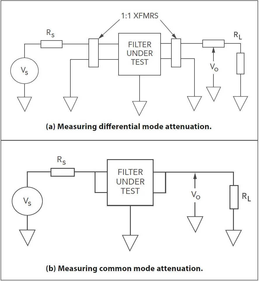
Figure 1
Beyond conducted emissions, an EMI filter may also provide some benefits to other compliance testing features, and aspects of performance which may not yet be covered by compliance standards. For example, EMI filter attenuation may extend below the 150kHz frequency used in many commercial standards.
This can be useful to know when noise and interference generated below 150kHz is causing performance or interference that may go unaccounted for. The following is a brief illumination on how EMI filters may impact other EMC emissions testing.
To design a good filter, the passband must be defined just as the potential interference frequencies. The level of anticipated interference should be approximated. Comparing this to the required EMC standard will yield the degree of necessary insertion loss or attenuation.
Unless the design engineer has experience in filter designing, it is recommended that such assistance be called upon from a potential filter manufacturer like Schaffner EMC, Inc. EMI test laboratories can also provide many filter choices.
No load/Full load
The filter’s insertion loss or attenuation characteristics should be verified not just at the 'no load', but for the 'full load' current levels as well (see Figure 2).
Since inductors are one of the key components in the filter, it is important to note that variables such as the type of core material and saturation current level through the inductor can affect the value of the choke. Using the smallest L value possible and keeping the inductor ESR small will help. For more information, see the Rated Current section below.
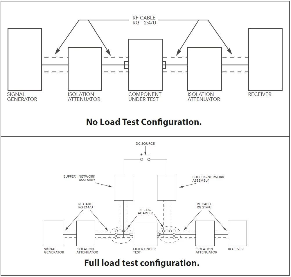
Figure 2
Rated current/Current Overload/Leakage or Reactive Current
Rated Current - The rated current should be equal to the maximum input current to be drawn from the device being filtered. Chokes consist of an electrical conductor wound around a material with magnetic characteristics, the core. The choke always makes use of its magnetic characteristics to suppress RF noise. The core material determines the performance of a choke.
It enhances the magnetic effects in the choke, improves the suppression characteristics and leads to more compact components. Core materials are also dependent on outside factors such as temperature or current. When used outside of its specified current range, a choke can saturate, leaving it unable to supply its original impedance (see Figure 3).
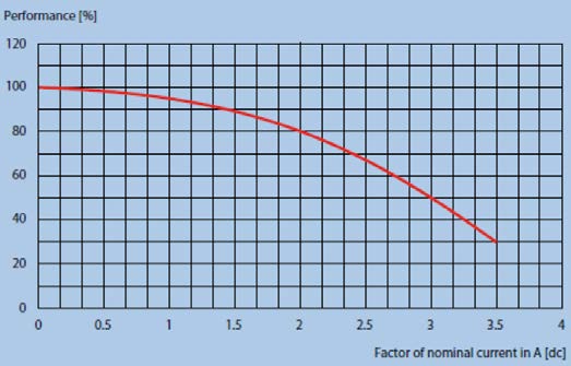
Figure 3
Current Overload - Current overload characteristic of a filter demonstrates the filter’s ability to withstand the heat dissipated by the filter’s components when subjected to a higher than rated current of the filter.
Typically, it is performed per paragraph 4.6.10 of MIL-F-15733 at 140% of the rated current under rated frequency for 15 minutes. After the required time period, insulation resistance and voltage drop (see Figures 5 and 7) must be repeated.
When the power is turned on, current begins to flow, and the initial current flow reaches a peak current value that is larger than the steady-state current value. Following this, the current value gradually decreases until it stabilises at the steady-state current. The part during which a large current flows before reaching the steady-state current is the inrush current.
If the size of the inrush current exceeds that allowed by the part in use, depending on the magnitude of the inrush current (difference between the peak current value and the steady-state current value) and length of its duration (the length of time until the peak current value converges with the steady-state current value, hereafter called the pulse width), the part used in the circuit may overheat, potentially causing the electrical device to malfunction or break down.
Leakage Current - During normal operation of electrical equipment, some current flows to earth. Such currents, called leakage currents, pose a potential safety risk to the user and are therefore limited by most current product safety standards. Examples for these standards are EN 60950-1 for information technology equipment, IEC60601 for medical equipment or UL 1283 for passive EMI filters.
The standards include limits for the maximum allowed leakage current. The typical leakage current values for a Class I device (protective earth) are 300μA in a patient-care area and 500μA outside that area. For a Class II device (double insulated), the values are 150μA in a patient-care area and 250μA outside that area.
For passive EMI filters it is common to calculate the leakage currents based on the capacitor values against earth and other parasitic components. This leakage current is limited by the international safety agencies to prevent a danger to personal safety.
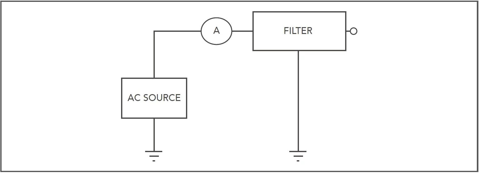
Figure 4
Rated Frequency
The frequency of the AC mains supply is either 50 or 60Hz. The operating frequency of the filter is determined by the behaviour of the capacitors. Depending on the voltage/frequency characteristic of the capacitor, it might be possible to operate a filter at a higher frequency but with a reduced input voltage.
Rated voltage/Voltage Drop/Overshoots
Rated Voltage - The rating voltage should be equal to or greater than the maximum input voltage to be supplied to the device being filtered. The rated voltage of the filter defines the maximum continuous operating voltage, i.e., the maximum voltage at which the filter should be used continuously.
Short overvoltages are permitted in accordance with IEC 60939, but to avoid damage to the filter capacitors, the continuous voltage should not exceed the rated voltage for an extended period of time.
Voltage Drop - The impedance of the filter is measured at the relevant power network frequency, i.e., 50Hz for European applications and 60Hz for North American applications.
This is performed at a defined temperature, such as 25°C. Current flowing through this impedance, of course, will cause a voltage drop across the filter resulting in a change in the voltage seen at the load end of the filter.
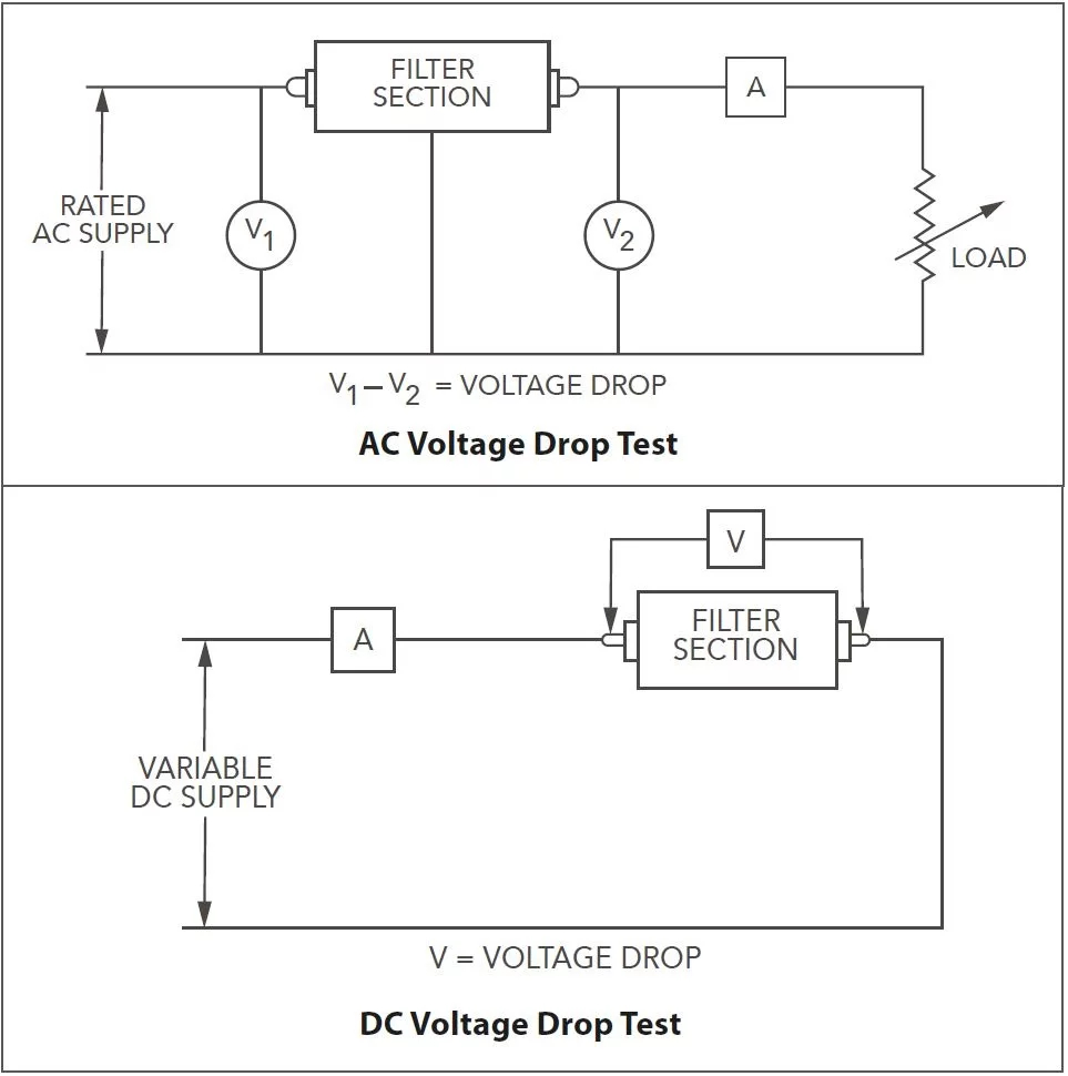
Figure 5
Overshoots - Voltage overshoots and voltage peaks can come with high dv/dt values but are also a problem on their own. The inductance of the filter acts like a choke according to the energy storage principle. If chokes are subject to voltage pulses, voltage peaks occur every time switching on or off takes place.
The higher the energy content (inductance) of the choke, the higher these voltage peaks become. These amplitudes can, in turn, reach values that cause a stress situation in the winding insulation.
Dielectric withstand
Dielectric testing, sometimes referred to as Hi-Pot testing, demonstrates the ability of the filter capacitors to ensure higher than rated voltage. In filters, components are used that are connected between the phases of the supply network or between one phase and earth. It is therefore important to determine how well filters resist high voltages.
A dielectric withstand test is performed for this reason by applying a voltage between enclosure and phase or between two connectors for a defined time. The current flowing between the same points is measured. Current flow means that the insulation is broken; the equipment fails the test.
During approval procedures, the test is usually performed over a longer period (typically one minute) with a defined voltage. Many safety standards require the testing to be performed on 100% of all units, but to save time, a test with higher voltage but reduced time is accepted. It should be noted that repeated high voltage testing can lead to a damage of the insulation.
Please note that this test is a high stress test for the capacitors inside the filter. Each additional test stresses the capacitors again and leads to a reduction of life time. Schaffner recommends keeping the number of tests to a minimum and never test the filters at higher than the indicated voltages.

Figure 6
Insulation Resistance
Insulation resistance indicates quality of the filter capacitor construction and filter insulation system. Low insulation resistance may indicate a condition which may lead to possible deterioration over time. Sometimes this can be calculated from measurements of the DC leakage current at the specified voltage.
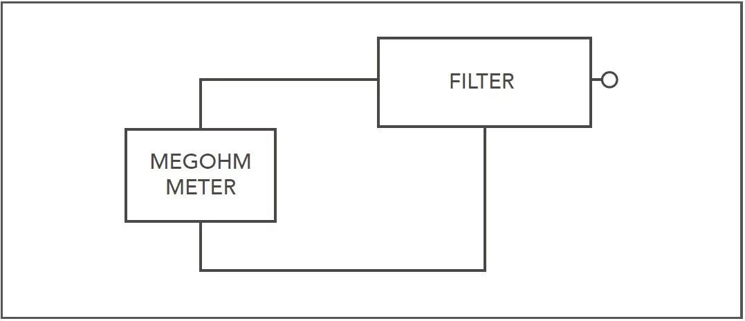
Figure 7
Final thoughts
Schaffner not only can provide off the shelf EMC filter solutions but also support manufacturers with their EMC layout from the early stages of new product ideas or designs. Schaffner can also offer custom made solutions to help manufacturers meet any unique electrical, mechanical or EMC challenge. Contact your nearest Schaffner representative for assistance.
References
- Electromagnetic Compatibility Engineering, Henry W. Ott, John Wiley & Sons, Inc. Publisher, 2009.
- Testing for EMC Compliance, Mark I. Montrose and Edward M. Nakauchi, IEEE Press & Wiley - Interscience, 2004.
Similar articles

More from Schaffner Ltd
- Schaffner (re)shapes electrical power through Industry 4.0 7th November 2019
- The need for EMI filtering with factory automation 7th November 2019
- LCL filters aid energy regeneration requirements 14th January 2019
- Power products unveiled at SPS IPC Drives 2017 6th November 2017


Write a comment
No comments