
New TESEQ ESD Simulator Features Built-In Discharge Relay
2nd November 2011
Teseq has introduced the NSG 438A a new ESD simulator that includes an integrated discharge relay circuit to dissipate residual voltage in conventional ESD testing and ungrounded equipment under test (EUT) applications.
The relay in the new simulator provides unique controlled and reproducible discharge and observation time periods along with a discharge operation that is programmable in three separate time segments. It can also be retrofitted into any existing Teseq NSG 438 or NSG 439. By connecting a 1 MΩ resistor from the EUT to ground for a controlled time segment that dissipates the residual voltage, the NSG 438A has set new benchmarks in flexibility and reproducibility of EMC testing.
The easy-to-use, IEC EN61000-4-2-compliant unit makes discharging EUTs safe and efficient, while comprehensively fulfilling many automotive, household and industry test standard requirements, including ISO 10605.
Teseq’s new ESD simulator offers flexible control parameters for both the built-in and external EUT discharging circuit. It features three freely programmable time parameters that allow the charge holding time to be precisely defined.
The operator can simply set the discharge cycle time and the associated repetition intervals of the ESD pulses so that any residual voltage is guaranteed to be removed from the EUT. The sum of all three time segments equals the pulse repetition rate, an adjustable rate ranging from 0.1 seconds to 99 seconds in intervals of 0.1 seconds.
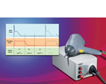
By setting the relay closing or opening time with the ESD simulator’s touch panel, users can monitor all three independent EUT discharge time segments. The segments are defined into three categories – T1, T2 and T3.
During T1, the ESD pulse energy is maintained or bleeds off from the EUT within the context of an ordinary discharge event. The discharge relay closes in order to remove the residual charge once the preselected time expires.
T2 defines how long the complete discharge phase should last, determined by the environment, the EUT’s design and the test procedure being performed. The simulator’s tip is connected to ground via a 1MΩ resistor.
Segment T3 is when the discharge path relay opens. This period may be used to verify EUT’s function. Once the time has been completed, the cycle begins again.
The easy-to-use, IEC EN61000-4-2-compliant unit makes discharging EUTs safe and efficient, while comprehensively fulfilling many automotive, household and industry test standard requirements, including ISO 10605.
Teseq’s new ESD simulator offers flexible control parameters for both the built-in and external EUT discharging circuit. It features three freely programmable time parameters that allow the charge holding time to be precisely defined.
The operator can simply set the discharge cycle time and the associated repetition intervals of the ESD pulses so that any residual voltage is guaranteed to be removed from the EUT. The sum of all three time segments equals the pulse repetition rate, an adjustable rate ranging from 0.1 seconds to 99 seconds in intervals of 0.1 seconds.
By setting the relay closing or opening time with the ESD simulator’s touch panel, users can monitor all three independent EUT discharge time segments. The segments are defined into three categories – T1, T2 and T3.
During T1, the ESD pulse energy is maintained or bleeds off from the EUT within the context of an ordinary discharge event. The discharge relay closes in order to remove the residual charge once the preselected time expires.
T2 defines how long the complete discharge phase should last, determined by the environment, the EUT’s design and the test procedure being performed. The simulator’s tip is connected to ground via a 1MΩ resistor.
Segment T3 is when the discharge path relay opens. This period may be used to verify EUT’s function. Once the time has been completed, the cycle begins again.
Similar articles

More from
- New Development Kit from Teseq Helps Build Personalised Pulse Networks 10th May 2012
- Teseq UK Calibration Service Covers All EMC Test Products and Antennas 27th April 2012
- Teseq Holding AG Acquires MILMEGA to Expand RF Power Amplifier Capabilities 23rd February 2012
- New TESEQ USB Controlled Power Meter Operates Over 9 kHz to 3 GHz 21st December 2011
Product Centre Updates


2024 World Battery & Energy Storage Industry Expo (WBE)
8th August 2024
China 1st and 2nd Floor, Area A, China Import and Export Fair Complex
Write a comment
No comments