
The life inside a toolbox
Each and every tool in a toolbox has a purpose, a specific function and certain parameters of use to achieve a desired outcome. When you pull out a claw hammer, your intent is to drive or pull a nail. Pull out a ball peen hammer, it is still a hammer, however the use and outcome is different. You may be flattening a piece of metal or straightening a bracket that got damaged.
They are both hammers, but the manner in which you use them to achieve a desired outcome is slightly different.
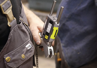
This is also the case with laser alignment systems used for precision shaft alignment or geometric measurements. Different manufacturing and designs have subtly different requirements to achieve the desired outcome. One of the primary elements of laser alignment of rotating machinery is the placement and control of the sensor/detector heads. Improper placement or handling can lead to difficulty in maintaining repeatable, accurate measurements. While all lasers brands are trying to achieve the same result, the process of alignment varies.
Different aspects of each design affect how we must handle the process to achieve the desired result, which is accurate measurement of the rotational shaft centrelines. Some systems will utilise single lasers with a mirror or prism, while others such as Fixturlaser tools use two laser beams. The way these designs are handled in the measurement process is quite different with specific aspects of control taking on importance.
Addressing the proper placement and control of the sensors of Fixturlaser systems, one of the benefits of using Fixturlaser tools is the legacy aspect. All Fixturlaser tools are intuitive to use making the precision shaft alignment process easier and of course without sacrificing accuracy. All the systems are handled the same way. If you learn on any one of the tools, you will be able to operate the other tools. The process and base functions are virtually identical in nature.
Properly measuring using Fixturlaser alignment tools: What matters?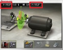
- Measurement position of the sensors and measurement methods
- Distance between sensors
- Angular Relationship (inclinometers)
- Bracket assemblies
- Mounting Location
- Miscellaneous possible looseness
These all show importance as all these aspects are about controlling movement of the sensors and repeatability in actions.
Measurement positions and measuring methods
- Some Fixturlaser tools have optional measuring methods that allow measurements to be taken in any position. There can be three possible choices; Tripoint, Express and Clock methods. Tripoint and Express allow measurements to be taken in any position, Express measures automatically in any position. Clock method requires the sensors to be in clock positions. There are specific times where each of these methods are useful. Most alignments can be performed in the Tripoint or Express method.
- When using Tripoint or Express measuring methods, alignment readings can be taken in as little as 60° of rotation if needed.
Distance
- Mounting distance between the sensors can be from almost touching to up to 10m (just under 33ft.), depending on the system.
Angular Relationship
- In most tools, there are inclinometers built in the sensors. The inclinometers measure the radial position of the sensors allowing measurements to be taken at any position in the rotational arc. The inclinometer values are found at the top of the screen on the Display Unit. They are the outer numbers, extreme right and left respectively. In the photo, both the stationary and moveable sensors are at 165.8°.
- The inclinometer values are part of the misalignment calculations. Although the tool will allow for greater deviation try to maintain no more than 0.5° degree of separation between the relative position of the heads if possible.
Mounting Location
- The sensors only require that the stationary machine be represented by the stationary sensor and the moveable machine is represented by the movable sensor. Both sensors must be mounted solidly and free of obstruction of the light beam. Each sensor can be mounted on the shaft, coupling hub, fly wheel or brake disc. Anywhere that will represent that piece of equipment and the shaft rotational centreline. You can mount the sensor using chain brackets, mag brackets, extensions, but be sure that whichever mounting option you choose does not allow for unintended movement of the sensor during the alignment process.
Brackets and General Looseness
- Brackets are built to be versatile using interchangeable components. Therefore, care must be taken in the assembly of the bracket to eliminate unintended movement. Be sure that all components are tightened using the supplied tool.
- Insure that brackets are tight on the shaft or hub. If you can slide the bracket on the shaft it is not tight enough.
- Be certain that the positioning clips on the sensors are fully engaged and the lock nut on the adjuster screw on the moveable sensor is locked.
As stated previously, when measuring in minuscule amounts unintentional movement must be controlled. Every aspect pointed out here is about maintaining control of the machines to be aligned and the sensors mounted to them. Proper technique (sensor control) will help you to obtain accurate readings that can translate into efficient (fewer) movements or corrections using the Verti-Zontal Process for a fast alignment.
Similar articles

More from Fixturlaser AB
- Vibration analysis: Where to start? 8th January 2020
- Is this soft foot or are you pulling my leg? 15th February 2018
- It's not the machine, it's you! 4th July 2017
- Roughing in before precision shaft alignment 2nd June 2017


Write a comment
No comments