
A practical approach to servo loop tuning
With an unquestionable performance capability, servo motors and their final performance is mostly determined by the servo loop tuning. Making servo motors attractive for use in closed loop systems, is the ability to create torque in a linearly predictable fashion. Despite the wealth of theoretical material regarding closed loop systems and closed loop control, tuning a PID servo loop continues to be a bit of an art.
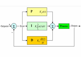
The PID Controller
The PID controller is one of the most used control algorithms in any closed loop system.
The PID controller derives its name from the 3 component: Proportional term, a term resulting in an output signal that is proportional to the process error. The Integral term, this is an output signal that is the integral of the process error. Derivative term, that results in an output signal that is the derivative of the process error.
In general, these 3 terms act independently from each other and their outputs are summed together to create a single PID output signal.
Other configurations are possible as well. For example, derivative term may act only on the feedback (output) signal, not the error signal, with proportional term in parallel with integral term.
In motion control application process error, described above, is difference between desired and actual motor positions, i.e. position error.
Effect of the PID Terms
With a practical tuning exercise and the real effect of the various gains, digital servo drive and motor with encoder feedback will be used to illustrate the effects of the various gains, as well as to provide some practical guidelines.
One of the best ways to evaluate PID tuning, is to look at the step response of a system. In order to make sure that the system does not saturate and to avoid strong nonlinearities, small signal excitation and its response will be used. In addition to looking at the position response, torque will also be observed, as a measure of ‘how hard we are driving’.
If friction is added to the system, damping characteristics will improve, but larger gains will be required. Addition of the friction will introduce small steady state error, not allowing the system to reach final target position.
This should always be the first step in servo loop tuning. Start with just proportional gain and look at the response.
If the system has a tendency to overshoot quickly, even with small gain, likely the friction is low.
If more gain is required to get any response, and the response is slow, the system has considerable friction. This determines the next step.
Low Friction System – Effect of Derivative Term
In a low friction system, the response has a tendency to become unstable quickly, even with low gains.
To remedy this instability, derivative action is required. Because the D term differentiates the position error which changes fast in case of instability it helps suppress the large changes by creating an opposing torque. In the system above, with the same proportional gain and with some derivative gain following response is obtained.
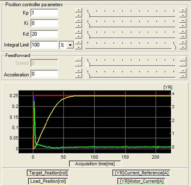
Large overshoot now is eliminated. However, the overall response is also slower (meaning the time required to reach the target).
Frictional System – Effect of Integral Term
As noted above, by just using a proportional term, a stable response can be obtained, however the final target is not reached.
With added integral term, the longer the error exists, the larger the integral will become, resulting in a correction torque. In the system above, with the same proportional gain, and with added integral gain, position error (steady state error) is reduced to zero, even in the presence of friction.
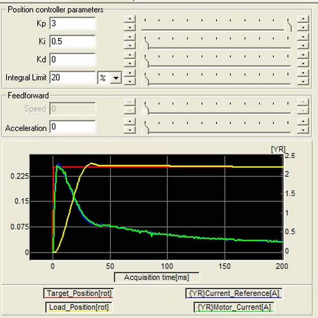
Integral limit (also called anti-windup) should be used with an integral term, to avoid integral term from becoming too large and taking too long to converge down.
PID Combined
One can notice that in case of the P and D terms in a low friction system that the steady state error is nonzero. Also in case of the P and I terms in a frictional system, some overshoot is introduced. In all these cases we can add integral and derivative terms respectively.
Tuning Tradeoffs
From the response curves it is clear that in addition to the shape of the response, the response time is dramatically affected. Response curves have a few attributes that help quantify the response:
- Overshoot: by how much is the target position exceeded.
- Step response time: after how much time is 67% of the final target reached.
- Settling time: after how much time is the position settled within some % of the target.
Below is a system response as increasing the gains to obtain faster response:
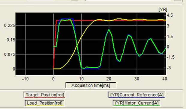
The current limit in the system is reached at 4A. Reaching this limit causes saturation and an ensuing oscillation (which does die out after coming out of saturation).
This means that motor and drive sizing should not only be based on the torque and speed requirements, but also on the required system response.
Mechanical transmission components should also be carefully selected to avoid system resonance (see previous article on the effect of coupling stiffness).
Lastly the feedback resolution should not just be based on positioning resolution requirements but also on desired system response.
Conclusion
Servo loop tuning is not a trivial task. A hand on experience is invaluable and above information will, hopefully, allow achieving the desired response.
Although the behaviour of the PID algorithm is well understood, there are many implementation details and system parameters that influence the response.
By utilising a systematic approach of increasing the proper gains gradually while monitoring the response, stable behaviour can be more quickly obtained.
In parallel, the current and torque should be observed to determine how much power is applied, or to avoid saturation. If the system is marginally sized, it may be necessary to adjust performance expectations.
Similar articles


More from IntelLiDrives, Inc.
- Compact actuators include SMART motors 8th August 2017
- H-gantry design with large THETA 1st November 2016
- Scanning stages include precision motorised ball screw 14th September 2016
- A practical approach to servo loop tuning 3rd August 2016


Write a comment
No comments