Understanding sensors within a fluid control system
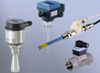
Very little can be achieved without raw data supplied by sensors in today's fluid control systems. These sensors can help facilitate a variety of tasks from displaying process information and performing control functions to operating alarms, but each one has to communicate information to a process controller. Bürkert's Kieran Bennett looks at the range of sensors available, the different technologies used in their design and how the application affects the specification.
Flow sensors
In any production control system it is crucial to know the quantity of fluid that is actively involved in the process and this is where the flow sensor needs to be able to accurately indicate the flow. There are a number of different designs which have particular characteristics, making them better suited to a specific application or fluid medium.
Paddle wheel designs require direct contact with the fluid and are better suited to fluids with very low solids content, especially media with similar characteristics to water. The paddle wheel, which contains permanent magnets, is caused to rotate by the fluid flow and this movement is detected by a Hall sensor located outside the fluid area. The integrated electronics then convert this into a square wave frequency signal, which can be used by the process controller.
For fluids with higher viscosity it may be more appropriate to use a volumetric measuring method, consisting of two inter-meshed oval gears, which are caused to rotate by the fluid flow. One of the gears contains a permanent magnet and the rotary motion is detected by a Hall sensor, which again can be transmitted as a square wave frequency signal. High levels of accuracy can be maintained with this system; however the margin for error increases with thinner fluids and lower flow rates.
Both of these designs can be used with aggressive fluids as well as with fluids at higher temperatures, providing that the internal components have been correctly specified. The construction of the paddle wheel and its bearings along with the sealing materials should be carefully considered against the characteristics of the fluid. Most sensor manufacturers should be able to offer advice and a range of options to ensure proper compatibility.
In situations where the fluid is more heavily contaminated but is classed as a conductive media, then the use of a magnetic inductive sensor, also known as a magmeter, may be more suitable. Using two electrodes and two solenoid coils, the flow of the fluid induces a voltage between the electrodes and this voltage can be amplified and converted into a standard signal. The voltage is directly proportional to the flow rate and as such provides very accurate flow data.
Increasingly, more applications require non-contact methods of measuring flow, especially with fluids at extreme temperatures and pressures; in these cases ultrasonic flow sensors can be used. Although these have been in use for some time, the technology has advanced considerably from single transmitters and receivers to multiple, combined units that use more advanced electronics to improve accuracy.
Current designs vary between manufacturers, but one example uses a pair of transducers, each working as a receiver and transmitter, located within the wall of the pipe at a specific distance. Both transducers simultaneously send out an acoustic wave signal, which is reflected by two mirrors in the fluid stream and then detected by the respective sensors.
Changes in the flow velocity affect the time taken for each signal to travel between the sensors; the greater the difference, the greater the flow. This signal is then converted into an analogue signal, which can be used by the process control software. Clearly, flow direction is important with this type of sensor and they should only be used where flow is unidirectional.
Level sensors
Storage vessels form a crucial part of any fluid control process and so accurate level detection is essential to enable the process controller to maintain normal levels and provide warnings if these parameters are exceeded. In some cases the process may involve very aggressive media or potentially explosive atmospheres, which would require careful specification of the level sensing equipment.
The ultrasonic level sensor is probably the most widely used non-contact sensor since it is very versatile and can be used to calculate volume and flow rates in open channels. The measurement principle is very simple, involving short ultrasonic pulses which are reflected off the surface of the media and the measured distance is interpreted as a continuous level measurement.
These sensors are well suited to aggressive media and modern designs allow for very precise measurement, even in vessels containing built-in fixtures which might otherwise disrupt the echo signal. Sensors can be specified to measure a wide range of distances as well as for operation within Ex-designated areas.
For applications requiring level measurement over a greater distance, then the use of radar level transmitters may be required, with capabilities up to 30 meters. These devices are usually very well protected and suitable for operation with aggressive media and high pressures as well as hygienic applications. The principle of measurement is very similar to the ultrasonic sensors but using very short radar pulses instead.
The guided microwave level transmitter is designed to operate with aggressive media and under high pressure, especially over larger distances, in some cases over 30m. A high frequency microwave pulse is guided along a steel cable or rod. When the pulse reached the media surface, it is reflected back and the internal electronics interpret the time taken into a distance. These sensors provide a continuous reading of the media level with the vessel.
Usually manufactured from stainless steel, these transmitters typically have ingress protection ratings of IP66 and above, with options to provide Ex versions where appropriate. Some sensors incorporate a visual display of the level as well as providing the level signal to the process controller.
For applications where there is turbulence, air bubbles or varying products, the tuning fork level sensor can be used to detect overfill or to prevent dry-running. The tuning fork is peizo-electrically energised and vibrates at its mechanical resonance frequency of approximately 1200 Hz. When the fork is submerged in the media, the frequency changes and this change is detected by the internal oscillator and converted into a digital output signal.
Pressure Sensors
The use of hydrostatic pressure measurements can also determine fluid levels within a tank. Essentially, fluid within a tank generates a specific hydrostatic pressure based on level and fluid density. By measuring this pressure with respect to a reference pressure, which is usually ambient pressure, the level can be determined, assuming that the fluid density is known.
It is also possible to use this method within a pressurised vessel by using a second sensor to measure the gauge pressure above the fluid level. Using these two pressure measurements, it is possible to evaluate an accurate level measurement. Accuracy is dependent on the precision of the pressure sensor, however, higher internal pressures within the tank increase the margin of error as will the use of two sensors, which compounds the original tolerance values.
Various designs of pressure sensor are available to suit a variety of applications. A piezo-resistive sensor is filled with hydraulic fluid to provide protection for the sensor. External pressure is sensed through the diaphragm by a change in the pressure of the hydraulic fluid. The sensor produces a pressure-proportional signal which is converted to the conventional analogue 4-20 mA output signal. This device is very well suited to low pressure measurement, while also able to withstand high overload factors.
A thin-film strain gauge provides very precise measurements as well as very high burst pressure characteristics. This design uses a thin-film Wheatstone bridge to measure changes in resistance caused by external pressure and converts these measurements into an analogue output signal which is proportional to the pressure.
For applications involving aggressive media or higher pressures, a thick-film ceramic measuring cell could be used. In this case the Wheatstone bridge is bonded to a ceramic diaphragm, providing greater protection and improved chemical resistance. However, the measuring accuracy is not as high as that of the thin-film strain gauge.
Temperature Sensors
The technology in temperature sensors has remained steady for some time, the developments have been made in the materials, both for the sensor body and the seals to allow operation in more aggressive fluids. The key is selecting the correct design of sensor based on the operating range and the environment in which it needs to perform.
The crucial aspect to making the correct decisions with regard to sensor selection is to ensure that all the information concerning the process to be controlled is available. Manufacturers, such as Bürkert, have a wide range of products to suit a vast array of industries and applications, with experts on hand to provide technical information and support.
With advances in materials technology and in the communication abilities of modern sensors, it is vital to understand the application and how it is controlled in order to ensure the best decisions are made. From the most basic level control systems to fully integrated, PLC controlled production processes, sensors play a vital role in providing essential information to the system controllers, therefore reliable operation is key. Bürkert Fluid Control Systems offers free training courses on this and many other subjects to help all those involved in the specification and operation of fluid control systems.
Similar articles
More from Burkert Fluid Control Systems
- Continuous water quality analysis for boreholes 6th July 2020
- Controller delivers precision microlitre dosing 14th May 2020
- Multi-medium testing facility for fluidic components 19th March 2020
- Micro precision for time-pressure dosing 10th December 2019




Write a comment
No comments